
Introduction: A Shop Floor Moment, Some Numbers, and a Question
I was on a factory floor last month watching a technician swap a drive while the line hummed — you know that moment where everyone holds their breath. Electrical Motor Products were stacked like puzzle pieces around us, and the replacement reduced downtime by a surprising 18% in that shift alone. (Small wins add up.) So here’s the question I kept asking: why do some motor systems still behave like stubborn old engines when we’ve got modern electronics and control theory on our side?
We see data: rising torque demands, tighter positional tolerances, and supply-chain quirks. I want to walk through where things trip up and what we can do about it. Let’s peel back the cover and get practical — the next section digs into the real technical pain points.
Digging Deeper: Why the ac motor and controller Setup Still Trips Us Up
What undermines otherwise solid designs?
ac motor and controller systems look simple on paper, but layers of interaction — inverter switching, encoder feedback, and field-oriented control loops — create subtle faults in the real world. From my experience, traditional solutions lean too heavily on basic V/f schemes or underpowered inverters, which struggle with torque ripple and thermal limits under variable loads. The result: jitter, unexpected stalls, and excessive heat. Look, it’s simpler than you think when you see the waveform distortions on an oscilloscope.
Technically, PWM artifacts and improper tuning of the controller can amplify mechanical resonance. I’ve seen installations where a misconfigured encoder or bad sampling timing caused position drift that nobody blamed on the control side — until we swapped to a properly tuned FOC loop and the problem vanished. That change cut reject rates and reduced after-hours fixes. Bottom line: the flaw isn’t always the motor; often it’s how the controller and power electronics cooperate (or fail to).
Forward-Looking Comparison: Where motor control products Are Headed
What’s Next?
When I evaluate new solutions, I compare principles rather than brand names. Modern approaches center on smart inverters, integrated sensors, and closed-loop control that behaves predictably under disturbance. New architectures emphasize predictive torque control and tighter integration between power converters and firmware — so the system adapts instead of reacting. I believe this shift will reduce the “mystery failures” we used to chalk up to bad luck — funny how that works, right?
Take one practical thread: modular motor control products that pair scalable inverters with embedded FOC and real-time diagnostics. These systems give you cleaner torque delivery, lower EMI, and actionable alerts before a failure — which I find more valuable than raw horsepower alone. In short, smart diagnostics plus robust control smooth out operations and save labor (and headaches). If you want to pick a system, here are three metrics I always weigh:
1) Control responsiveness — loop bandwidth and latency under load. 2) Thermal margin — real power headroom, not just nameplate ratings. 3) Diagnostic depth — what faults the unit reports and how early. Use those when you compare options; they tell you more than peak current specs.
Closing Thoughts and Practical Takeaway
I’ll be candid: I’ve grown skeptical of one-size-fits-all claims. We need gear that matches the real duty cycle, not marketing slides. Evaluate how a controller manages transient loads, how an inverter performs at partial duty, and whether the product gives you useful telemetry. Those three metrics translate to fewer emergency calls and better uptime.
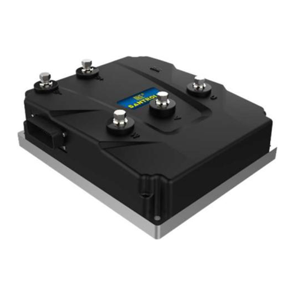
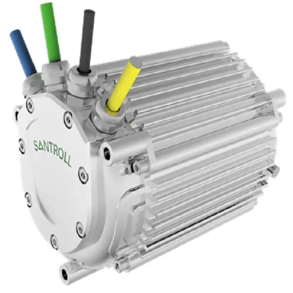
So yes — I prefer systems that are honest about limits and generous with diagnostics. That pragmatic approach has saved me time and money on multiple installs. If you want a starting point for comparison and sourcing, check out Santroll — they have a practical lineup that reflects these priorities.